 TR
TR  EN
EN  AR
AR  ZH
ZH  FR
FR  DE
DE  IT
IT  PT
PT  RU
RU  ES
ES  UK
UK  Can Durağan
 Using Strips in Grounding Systems: Basic Grounding Strip and Application Guide
The main grounding strip and other grounding elements are crucial safety measures in electrical systems. This method involves connecting the casings of electrical devices to a grounding system with a conductor buried in the ground to protect against any electrical leakage hazards. Thus, if there is an electrical leak in the device, the electric current will pass through the lower-resistance ground wire instead of through the person, eliminating the risk of electric shock.
What is a grounding strip? Where is it used?
Grounding strips are flat and flexible conductive elements used to establish an electrical connection with the earth in electrical systems. They are generally made of galvanized steel, copper, or stainless steel and are produced in various sizes. These strips have high conductivity and provide better contact with the earth thanks to their large surface area.
Basic grounding strip applications are encountered in various fields. They are frequently used in buildings, factory facilities, gas stations, lightning protection systems, and transformer substations. In particular, they are placed within the reinforced concrete foundations of buildings to provide overall grounding. They are also commonly used in electrical panels, generator rooms, and data processing centers for potential equalization purposes.
Grounding strips are produced in various sizes. The most commonly used sizes are 25x3 mm, 30x3 mm, 30x3.5 mm, and 40x4 mm. Material selection varies depending on the application area. However, galvanized strips are preferred due to their economic advantages and corrosion resistance. Copper strips, on the other hand, are used in areas containing sensitive electronic systems because they provide higher conductivity.
One of the most important points to consider in the installation of a basic grounding strip is its continuity. At the strip junctions, a low-resistance connection should be ensured using special connection elements of appropriate thickness. Furthermore, placing the strip at sufficient depth and with the correct techniques is critical for achieving the desired grounding resistance.
The biggest advantage of using strip grounding in a grounding system is that, thanks to its large surface area, it provides better contact with the ground, thus reducing grounding resistance. This ensures that in the event of an electrical leak, excess current is quickly transmitted to the ground, protecting life and property.
Foundation Grounding Strip: A Step to Take During Construction
The installation of a foundation grounding strip during construction is one of the most critical steps for ensuring the electrical safety of a building. This installation must be carried out during the foundation phase of building construction. It is virtually impossible to modify this process later.
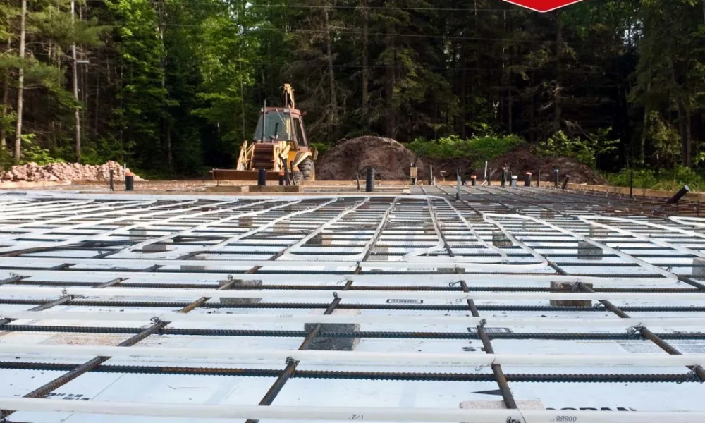
Firstly, the foundation grounding strip installation should be carried out before the foundation concrete is poured. The strip is placed at the very bottom of the foundation and around its outer perimeter, forming a closed ring. This creates a common grounding point for all electrical systems of the building. Additionally, the strip should be positioned so that it remains embedded in the concrete but also makes contact with the ground.
This step taken at the foundation stage has many advantages. First, thanks to the large surface area of the strip, contact with the soil is maximized. Low resistance values are obtained. In addition, the moisture retention property of the concrete increases the grounding efficiency, thus improving the effectiveness of the system. When properly installed, it is also more resistant to corrosion and other environmental effects that may occur over time.
The following points should be considered during the construction phase:
- Generally, 30x3.5 mm or 40x4 mm galvanized steel should be preferred as the strip material.
- The strip joints must be reinforced using special clamping pieces.
- Exit points should be provided inside the building for connection to the main distribution panel.
- At least two outlet points should be planned for grounding systems. This number can be increased according to project details.
These exit points are vital in case any intervention is required on the grounding strip during the building's later years of use. Therefore, this fundamental practice carried out during the construction phase is one of the most important factors determining the safety of the building throughout its entire electrical lifespan.
Grounding Strip Installation Stages
One of the crucial steps in establishing a safe electrical installation in a building is laying the foundation grounding strip . This process consists of steps that must be completed professionally, starting with the selection of the correct materials.
Before starting the installation process, the necessary materials must be prepared. Special clamping parts for strip connections, grounding terminals, and appropriate measuring devices should also be available. All these materials must comply with TS EN 62561-1 and TS EN 62561-2 standards.
The laying process begins at the lowest level of the foundation. First, the strip is laid to form a closed ring that will encircle the entire building foundation. When bending the strip at building corners is necessary, sharp angles should be avoided. Special clamps should be used for strip joint connections, overlapping by at least 5 cm. These should be secured with bolted connections.
It is critical that the strip is positioned to maximize its contact with the ground. Furthermore, the strip should be embedded in concrete but still in contact with the ground. The strip embedded in the concrete should be connected to the ground via a copper conductor. Otherwise, the galvanized strip will corrode, increasing the grounding resistance. The exit terminals to be used at different points in the building for the grounding system should also be considered at this stage.
After the installation is complete, measurements must be taken. The grounding resistance should be calculated according to standards, and the measurement results should be below the specified value. If this value cannot be achieved, support with grounding rods or chemical grounding materials can be used.
Another important consideration during the installation process is establishing a connection between the grounding strip and the metal structural elements. The building's steel structure, water pipes, and other metal components must be connected to the grounding system via a potential equalization bar.
Finally, after the installation is complete, the integrity of all connections should be checked. It is important to prepare and keep a diagram of the grounding system. This will greatly facilitate future maintenance and inspections.
Common Mistakes and Correct Practices
Many critical errors can occur in basic grounding strip installations. These errors can severely reduce the system's effectiveness. Knowing these problems, frequently encountered by professional electricians, is vital for a safe system installation.
One of the most common mistakes is incorrect selection of strip material. Using materials that are not corrosion-resistant or substandard leads to the deterioration of the grounding system over time. Instead, durable and highly conductive materials such as hot-dip galvanized steel or copper should be preferred. Insufficient strip thickness is also a common problem.
Errors at connection points also reduce the efficiency of grounding systems. Failure to use bolted connections instead of welding at strip splice connections, or insufficient tightness at connection points, increases resistance. To facilitate easy installation of terminal bolts at connection points, Esco has designed a Locking Type Practical Bolt Terminal with a Utility Model Certificate. For correct application, the strips must overlap by at least 5 cm and be secured with special terminals.
Errors in the depth of grounding strip installation are another source of problems. Laying the grounding strip too close to the surface makes it more susceptible to mechanical damage and more affected by seasonal humidity changes. The ideal depth should be below freezing and at a level with sufficient moisture.
Ring formation errors are also an issue that requires attention. The grounding strip must surround the entire structure and form a closed circuit. An open or incomplete ring significantly reduces the efficiency of the system.
Correct Practices
The foundation grounding electrode should be installed so that it is completely covered with concrete. After the foundation concrete is poured, it should be placed at least 5 cm deep in the concrete in all directions. The end points should be placed outside the foundation. The protruding wires should not be in contact with the soil; a copper conductor should be used in the soil.
Galvanized strips should be connected to copper ring conductors or copper grounding electrodes using neutral terminals that have corrosion-retardant properties. Contact between different metals accelerates corrosion.
In buildings with a large footprint, the area enclosed by the foundation ground electrode should be divided into 20m x 20m bays using transverse connections.
In areas where foundation grounding is implemented, a "potential equalization bar" must be installed.
The necessary equipment for disconnecting grounding conductors during grounding resistance measurement should be located in easily accessible places.
The foundation grounding also serves as grounding in lightning protection systems. For this purpose, outlets are provided around the building. These outlets can be made of steel strips or cables. The cable cross-section must be at least 50 mm² (NYY).
Lack of maintenance and neglecting periodic checks lead to an increase in grounding resistance in the long term. The grounding system should be checked at least once a year by taking measurements and recording the values.
To avoid faulty installations, it is essential to work with expert electrical engineers or qualified installers and to follow current standards. A correctly installed foundation grounding strip is a guarantee of life and property safety.
Frequently Asked Questions (FAQ)
What is a grounding strip and how does it work?
A grounding strip is a flat and flexible conductive element used to ensure safety in electrical systems. In the event of a possible electrical leak, it protects people and devices by conducting the dangerous current to the ground.
What are the ideal dimensions for a basic grounding strip?
The most common sizes for foundation grounding strips are 30x3.5 mm or 40x4 mm. These dimensions provide sufficient conductivity and durability.
Where and how should the grounding strip be installed?
The grounding strip should be installed at the lowest level during the building's foundation phase, forming a closed ring around its outer perimeter. The strip should remain embedded in the concrete but also be properly connected to the ground.
How should grounding strips be maintained?
Grounding systems should be checked and measured at least once a year. Regular maintenance and checks maintain the system's effectiveness.
What are the most common mistakes made in grounding strip installation?
The most common mistakes include selecting unsuitable materials, inadequate connection points, laying at the wrong depth, and failing to create a closed loop. To avoid these mistakes, it is important to work with qualified electricians and follow current standards.
